Description
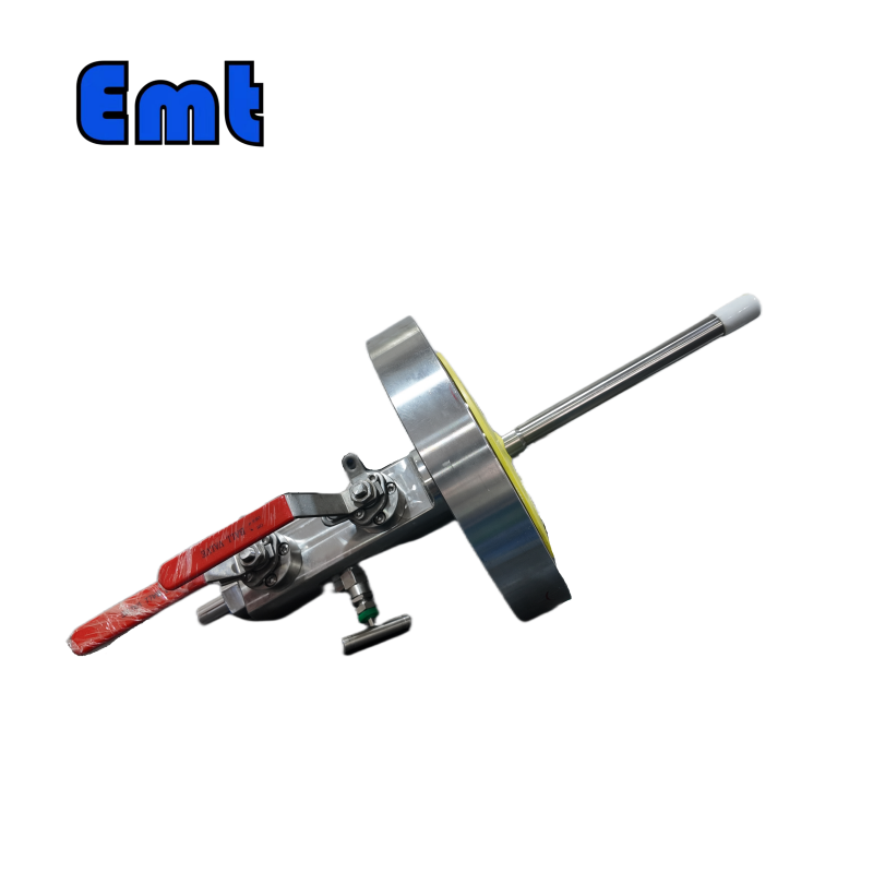
The Injection Quill Assembly is a critical component in chemical injection and sampling systems, serving as the primary point for introducing chemicals into pipelines or for extracting samples from the piping medium. This assembly is engineered to periodically inject chemical inhibitors, crucial for reducing or managing corrosion within pipelines, thereby preserving the longevity and integrity of the systems.
The EMT Injection System offers straightforward and secure access for injecting inhibitors while the system is under pressure, promoting safety and efficiency during the operation. This system is designed to meet various operational demands, facilitating its integration into existing pipeline infrastructures without disruption.
Order Information
Injection Quill Assembly
| Model | ||||||
| EMT-CIPA | Injection Quill Assembly of Coupon, Injector, Probe assembly | |||||
| – The material of Access Fitting Body | ||||||
| 0 | CS | |||||
| 1 | 316SS | |||||
| 2 | 316LSS | |||||
| 3 | DUPLEX SS | |||||
| The Type of Access Fitting Body | ||||||
| B | 2″Welded(suffix “pressure rating” can be added to B) | |||||
| F | 2″ANSI Flange(suffix “pressure rating & sealing type” can be added to F) | |||||
| -Tee Size- pressure rating & sealing type if flanged end | ||||||
| 0 | No Tee | |||||
| 1 | 1/4″NPT(F)Tee | |||||
| 2 | 1/2″NPT(F)Tee | |||||
| 3 | 3/4″NPT(F)Tee | |||||
| 4 | 1″NPT(F)Tee | |||||
| 5 | Hole for 1/4″SWN Flange | |||||
| 6 | Hole for 1/2″SWN Flange | |||||
| 7 | Hole for 3/4″SWN Flange | |||||
| 8 | Hole for 1″SWN Flange | |||||
| -Protective Cover Type/ Material | ||||||
| 0 | No Protective Cover | Material | ||||
| 1 | Without hole | CS or 0 | ||||
| 2 | With hole | SS or 1 | ||||
| 3 | Bleed Valve | DSS or 3 | ||||
| 4 | Bleed Valve, & Pressure Gauge | |||||
| For Example:EMT-CIPA-0F600#RF-2-1/CS shows 2″ANSI 600#RF Flange Access Fitting Body in CS, 1/2″NPT(F)Tee, Protective Cover in CS without hole
0F600#RF: 0F_ Access Fitting Body is Flanged in CS , 600#RF _Size is 2″ANSI 600#RF , 2:Tee size is 1/2NPT(F) 1: Protective cover type is without hole /CS: Protective cove material in CS |
||||||
Sampler & Injector
| Injection Quill Assembly | |||||||||||||||||||||||||
| SI | Sampler & Injector | ||||||||||||||||||||||||
| -Code | Plug | ||||||||||||||||||||||||
| Pxxx | Type | Material | Sealing Material | ||||||||||||||||||||||
| 0 | No Request | 0 | CS | 0 | No Request | ||||||||||||||||||||
| 1 | Hollow Plug Body | 1 | 316SS | 3 | DSS | 1 | Viton O-Ring / PTFE Primary Packing | ||||||||||||||||||
| 2 | Solid Plug Body | 2 | 316LSS | 4 | INCONEL | 2 | HNBR | ||||||||||||||||||
| – Code | Injection Nut | ||||||||||||||||||||||||
| Nxx | Connection Size | Material | |||||||||||||||||||||||
| 0 | No Request | 0 | CS | ||||||||||||||||||||||
| 1 | 1/4″ | 1 | 316SS | 3 | DSS | ||||||||||||||||||||
| 2 | 1/2″ | 2 | 316LSS | 4 | INCONEL | ||||||||||||||||||||
| – Code | Sampling & Injection Tube | ||||||||||||||||||||||||
| Sxxx-Lx″ | Connection Size | Material | Nozzle | Line size(x″) | |||||||||||||||||||||
| 0 | No Request | 0 | CS | 0 | No Request | The most effective position for injection is generally at the center of the pipe | |||||||||||||||||||
| 1 | 1/4″ | 1 | 316SS | 1 | Open | ||||||||||||||||||||
| 2 | 1/2″ | 2 | 316LSS | 2 | Quill | ||||||||||||||||||||
| 3 | DSS | 3 | Cap & Core | ||||||||||||||||||||||
| 4 | INCONEL | ||||||||||||||||||||||||
| – Code | Type and Size of components connected to Tee and material of components | ||||||||||||||||||||||||
| Txx | Connection Size | Material | |||||||||||||||||||||||
| 0 | No Request | 0 | CS | ||||||||||||||||||||||
| 1 | 1/4″Nipple | a | 1/4″Nipple and Valve | 1 | 316SS | ||||||||||||||||||||
| 2 | 1/2″Nipple | b | 1/2″Nipple and Valve | 2 | 316LSS | ||||||||||||||||||||
| 3 | 3/4″Nipple | c | 3/4″Nipple and Valve | 3 | D SS | ||||||||||||||||||||
| 4 | 1″Nipple | d | 1″Nipple and Valve | 4 | INCONEL | ||||||||||||||||||||
| 5 | 1/4″SWN Flange* | e | 1/4″Nipple and Flange | ||||||||||||||||||||||
| 6 | 1/2″SWN Flange | f | 1/2″Nipple and Flange | ||||||||||||||||||||||
| 7 | 3/4″SWN Flange | g | 3/4″Nipple and Flange | ||||||||||||||||||||||
| 8 | 1″SWN Flange | h | 1″Nipple and Flange | ||||||||||||||||||||||
| For Example:SI-P221-N12-S122-L4″-T22 SI:Sampling & Injection Assembly,P221: Solid Plug Body in 316LSS Viton O-Ring and PTFE Primary Packing,N12:Injection Nut Connection Size is 1/4″and Material is 316LSS,S122:Injection Tube Connection Size is 1/4″ and Material is 316LSS.Type of nozzle is quill,L4″:For 4″pipe. T22: Connection Size of Nipple connected to Tee is 1/2″NPT(M), Nipple material is 316LSS | |||||||||||||||||||||||||
Note: SWN Flange is special WN Flange
Example for a set of Sampler & Injection Quill Assembly:
EMT-CIPA-0F600#RF-2-1+ SI-P221-N12-S122-L4″-T22
Design Features:
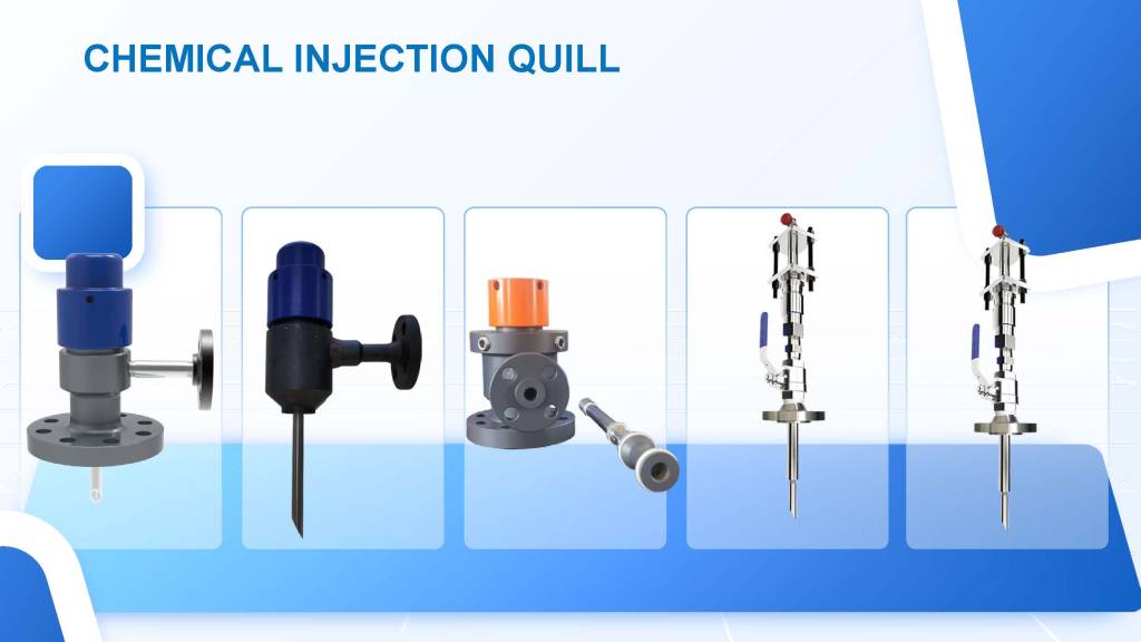
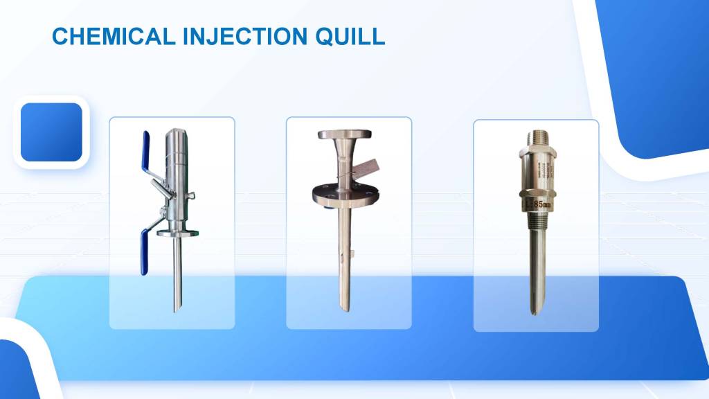
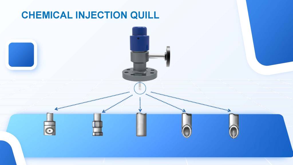
The Injection Quill Assembly boasts multiple nozzle types, each tailored to address specific application requirements effectively. These nozzles facilitate the precise delivery of chemicals, significantly enhancing the efficacy of inhibitors used in various processes. By ensuring accurate flow and distribution, the assembly maximizes the performance of the injected substances. Moreover, the design of the Injection Quill Assembly mirrors that of the sampler, promoting uniformity in both appearance and function. This consistency not only simplifies integration into existing systems but also reinforces reliability, making it an essential component for efficient chemical injection in pipeline operations.
Internal Components:
The core of the Injector and Sampler comprises a durable solid plug body, an injection nut, and an injection tube. This specific setup increases the assembly’s durability and reliability, thereby enabling it to endure the high-pressure conditions often encountered in industrial environments. Furthermore, the components are integrated into a Tee fitting that is equipped with NPT nipples, valves, and SWN flanges, which offers a range of connection possibilities to suit different piping systems.
Connection Sizes:
The Injection Quill Assembly supports a variety of process connection sizes, including:
- 2″ flange
- 2″ flare weld access fitting
- 1″ nipple to NPT ball valve
These connection options ensure that the assembly can be adapted to various pipeline specifications, simplifying installation and maintenance processes.
Operating Conditions:
Designed to operate within a temperature range of -20 ℃ to 150 ℃, the Injection Quill Assembly can effectively function in a wide array of environments. It is capable of handling pressures up to 6000 PSI, or as dictated by the flange size, making it suitable for high-pressure applications.
Reviews
There are no reviews yet.